
Introduction
Selecting the right control valve for your process is one of the most consequential engineering decisions made during any oil and gas, petrochemical, or industrial project. Get it right and your process runs efficiently, safely, and with minimal maintenance. Get it wrong and you face throttling instability, premature failure, cavitation damage, process upsets — and the cost of replacement under operating conditions.
This guide walks through the key selection criteria engineers and procurement teams must work through to specify a control valve that performs reliably across the full range of process conditions.
What Is a Control Valve and Why Does Selection Matter?
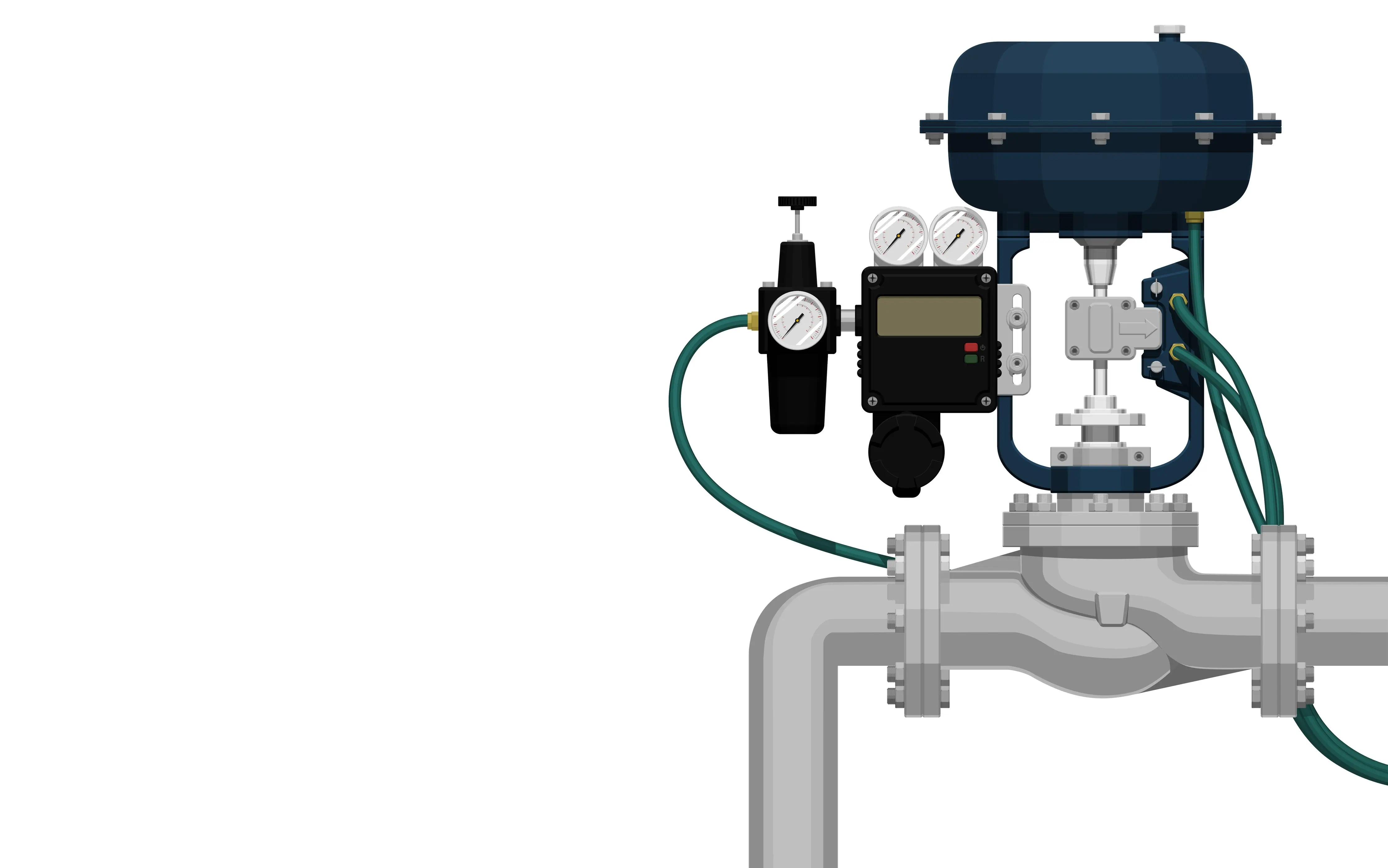
A control valve is a power-operated device that modulates the flow of a fluid — liquid, gas, steam, or slurry — in response to a signal from a controller. It is the final control element in a control loop, and its performance directly determines the quality of process regulation.
Unlike isolation valves, which are either open or closed, a control valve must operate continuously across a range of positions. This makes its selection far more complex. A valve that is oversized, undersized, or poorly matched to the process fluid will not control accurately — and in the worst cases, will damage itself and surrounding equipment.
The financial and operational consequences of incorrect control valve selection include:
- Inability to achieve stable process control, leading to product quality problems
- Cavitation or flashing that erodes the valve body and trim within months
- Excessive noise and vibration that affects nearby instrumentation and pipework
- Oversized valves operating at very low travel, accelerating seat wear
- Unplanned shutdowns and emergency replacements at significant cost
Getting the selection right from the start is always cheaper than fixing it during operations.
Step 1: Define Your Process Conditions Precisely
The foundation of correct control valve selection is a complete and accurate process data sheet. Before any valve type or size can be specified, the following process parameters must be established — at minimum, maximum, and normal operating conditions:
- Fluid type — liquid, gas, steam, two-phase, or slurry
- Flow rate — minimum controllable flow, normal flow, and maximum required flow (in volumetric or mass flow units)
- Inlet pressure (P1) — upstream pressure at the valve under all operating conditions
- Outlet pressure (P2) — downstream pressure, including back-pressure from downstream equipment
- Differential pressure (ΔP) — the pressure drop across the valve, which drives flow and sizing
- Fluid temperature — minimum, normal, and maximum, including any start-up or upset conditions
- Fluid density and viscosity — critical for liquid sizing calculations
- Vapour pressure — required for cavitation and flashing assessment in liquid services
- Molecular weight and compressibility factor (Z) — required for gas sizing calculations
Missing or approximate data at this stage leads directly to incorrect sizing and valve type selection. Always obtain process data from the verified process simulation or heat and material balance — not from estimates or previous project data.
Step 2: Calculate the Required Flow Coefficient (Cv)
The flow coefficient Cv (or Kv in metric units) is the fundamental sizing parameter for a control valve. It expresses the flow of water in US gallons per minute through a valve at a pressure drop of 1 psi. All control valve sizing standards — including IEC 60534 and ISA 75.01 — use Cv-based equations as their foundation.
For liquid service:
Cv is calculated based on flow rate, differential pressure, and fluid specific gravity. The calculation must also account for the possibility of choked flow — a condition where increasing differential pressure no longer increases flow because the fluid reaches its vapour pressure at the vena contracta and begins to flash.
For gas and steam service:
Cv calculation is more complex, incorporating inlet pressure, differential pressure ratio, gas compressibility, and molecular weight. Gas flow chokes when the pressure ratio across the valve reaches a critical threshold, typically around 0.5 for most valve types — beyond which flow cannot increase regardless of further pressure increase.
Sizing guidelines:
- The calculated Cv should fall between 20% and 80% of the selected valve's maximum Cv at normal flow conditions
- At minimum flow, the valve should be controllable above its minimum opening (typically 10% travel)
- At maximum flow, the valve should not need to open beyond 80–90% of its travel
A valve sized correctly within this range provides stable, responsive control across the full operating range.
Step 3: Assess Cavitation, Flashing, and Noise
For liquid services in particular, three damaging phenomena must be evaluated before selecting the valve body style and trim.
Cavitation
Cavitation occurs when the local pressure at the vena contracta drops below the fluid's vapour pressure, causing vapour bubbles to form. When these bubbles collapse as pressure recovers downstream, they release intense localised energy that erodes the valve body, seat, and trim — sometimes within weeks of operation.
Cavitation risk is assessed using the valve's liquid pressure recovery factor (FL) and the calculated cavitation index (sigma). If sigma falls below the valve's critical cavitation index, cavitation will occur and an anti-cavitation trim or a valve type with a higher FL value must be selected.
Flashing
If the downstream pressure also falls below the vapour pressure, the vapour bubbles do not collapse — they persist as a two-phase mixture through and downstream of the valve. This is flashing. While less damaging to the valve than cavitation, flashing causes high-velocity erosion of the valve body and outlet piping, and requires careful material selection and outlet velocity management.
Aerodynamic and hydrodynamic noise
High differential pressure across a control valve in gas, steam, or liquid service generates noise and vibration. Predicted sound pressure levels should be calculated per IEC 60534-8 standards. Where levels exceed acceptable limits (typically 85 dBA at 1 metre), noise-attenuating trim, downstream diffusers, or acoustic insulation must be specified.
Step 4: Select the Right Valve Body Type
With sizing, Cv, and flow regime established, the appropriate valve body type can be selected. The most common control valve body types in oil and gas and process industry applications are:
Globe Valve (Single-seated and Double-seated)
The globe valve is the most widely used control valve body type. Its linear plug-and-seat design provides excellent throttling control, a wide range of trim options including anti-cavitation and noise-attenuating designs, and compatibility with most process services. It is the default choice for the majority of general process control applications.
- Best suited for: moderate flow rates, precise control, liquid and gas services
- Advantages: wide trim availability, excellent rangeability, well-understood behaviour
- Limitations: higher pressure drop than rotary types, larger and heavier than equivalent rotary valves
Rotary Ball Valve (Control Type)
Characterised ball valves — including V-port and segmented ball designs — offer high flow capacity (Cv), low pressure drop in the open position, and compact installation. They are well suited to large-flow, low-pressure-drop services and to fluids containing solids or fibres.
- Best suited for: large flow, slurry service, high-capacity gas control, on/off with modulation
- Advantages: compact, lightweight, high Cv, suitable for dirty or viscous fluids
- Limitations: limited rangeability compared to globe valves, less precision at very low openings
Butterfly Valve (High-performance)
High-performance triple-offset butterfly valves provide tight shut-off with a low-torque design. They are used in large-diameter, high-pressure, and high-temperature services where globe valve weight and size become impractical.
- Best suited for: large diameters (DN150 and above), moderate control requirements
- Advantages: lightweight for size, low pressure drop, suitable for high pressures and temperatures
- Limitations: inherently non-linear flow characteristic, limited at very low or very high openings
Angle Valve
Angle valves are used where the process fluid enters from below and exits at 90 degrees. They are particularly suited to flashing and cavitating services, erosive fluids, and high-pressure-drop liquid applications because the flow path minimises the damage zone.
- Best suited for: flashing, cavitation, slurry, and erosive services
- Advantages: self-draining, handles difficult fluid conditions, can be fitted with specialised erosion-resistant trim
Step 5: Select the Flow Characteristic
The flow characteristic of a control valve describes the relationship between valve travel (stem position) and flow rate at constant differential pressure. Selecting the correct inherent characteristic is essential to achieving stable control loop performance.
The three main inherent characteristics are:
- Linear — flow changes proportionally to valve travel. Used where pressure drop across the valve remains relatively constant across the operating range.
- Equal percentage — each increment of travel produces an equal percentage change in existing flow. Used where pressure drop across the valve varies significantly with flow — the most common case in process plant applications. Equal percentage characteristic compensates for the system's natural tendency to reduce valve ΔP at high flows.
- Quick opening — large flow changes occur near the closed position, with flow approaching maximum at low travel. Used primarily for on/off and bypass applications, not for throttling control.
For most process control applications, equal percentage is the default recommended characteristic. The installed characteristic — which accounts for the varying system pressure drop — should be verified to confirm that the valve provides a reasonably linear installed gain across the operating range.
Step 6: Specify the Actuator and Positioner
The actuator and positioner are as important to control valve performance as the valve body itself. A correctly sized valve body with an undersized or poorly configured actuator will not control reliably.
Actuator selection
- Pneumatic spring-return actuators are the most common choice in process plants. They provide fail-safe action (fail-open or fail-closed on air loss), simple construction, and high reliability.
- Pneumatic double-acting actuators provide higher thrust and are used for large valves or high differential pressure services where spring-return actuators would be impractically large.
- Electric actuators are used where instrument air supply is unavailable or impractical, or where precise position holding is required. They are increasingly specified in offshore and remote applications.
- Hydraulic actuators provide the highest available thrust and are used for very large, high-pressure valves — common in pipeline and subsea applications.
Actuator sizing must account for the maximum differential pressure across the valve at the worst-case shut-off condition, friction in the packing, and any back-pressure on the actuator diaphragm. Under-sized actuators are a major cause of control valve failure in service.
Positioner selection
A smart digital positioner (electro-pneumatic) is standard practice on all modulating control valves today. Key considerations include:
- Communication protocol compatibility with the plant DCS (HART, Foundation Fieldbus, PROFIBUS PA)
- Partial stroke test capability for SIS/ESD valves
- Integrated diagnostics for condition monitoring and predictive maintenance
- Intrinsically safe or explosion-proof certification appropriate to the area classification
Step 7: Select Body Material and Trim
Material selection must be matched to the process fluid's corrosivity, temperature, erosiveness, and regulatory requirements.
Body materials commonly used:
- Carbon steel (ASTM A216 WCB) — general process service, non-corrosive fluids
- Stainless steel (CF8M / 316 equivalent) — corrosive fluids, sour service, food and pharmaceutical
- Duplex and super duplex stainless steel — high-chloride environments, seawater, aggressive chemicals
- Hastelloy C / Inconel — highly corrosive acids, high-temperature service
- Chrome-moly alloys (WC6, WC9) — high-temperature steam and hydrocarbon service
Trim materials:
Trim selection must address seat leakage class (per IEC 60534-4 or ANSI/FCI 70-2), erosion resistance, galling resistance, and temperature capability. Hardened trims (Stellite, tungsten carbide coating, hardened 17-4 PH stainless) are specified for erosive services. For sour service, materials must conform to NACE MR0175 / ISO 15156.
Packing selection:
PTFE packing is standard for most services. For high-temperature applications, graphite packing is used. For fugitive emission compliance (ISO 15848, TA Luft), low-emission packing designs with live-loading must be specified.
Common Control Valve Selection Mistakes to Avoid
Even experienced engineers make the following mistakes during control valve selection. Being aware of them prevents costly errors:
- Oversizing the valve — the most common mistake. An oversized valve operates at very low travel, making control difficult and accelerating seat wear. Always size to the process requirement, not to the line size.
- Using only normal flow conditions for sizing — the valve must be checked against minimum and maximum flow conditions, not just normal. A valve that works at normal flow but cannot achieve minimum controllable flow is unusable.
- Ignoring cavitation risk — specifying a standard globe valve on a high-pressure-drop liquid service without cavitation assessment is a guaranteed path to rapid trim failure.
- Selecting actuators on force alone — actuator sizing must account for packing friction, seat load, and worst-case shut-off ΔP. Sizing for normal operating force alone is insufficient.
- Specifying the wrong fail-safe action — whether the valve should fail open, fail closed, or fail in last position on signal or air loss must be confirmed with the process safety engineer and reflected in the P&ID.
- Not verifying rangeability — a valve with a rangeability of 50:1 sounds impressive, but if the process requires a turndown of 100:1, the valve cannot achieve the required minimum flow.
Control Valve Selection Checklist
Before finalising your control valve specification, confirm you have addressed the following:
- Complete process data sheet with min / normal / max conditions for all parameters
- Cv calculated per IEC 60534 at all flow conditions, with choked flow assessed
- Cavitation index calculated and compared to valve FL factor for liquid services
- Noise level predicted per IEC 60534-8 and within acceptable limits
- Valve body type selected and justified against process conditions
- Flow characteristic (linear, equal percentage) confirmed appropriate for the control loop
- Actuator sized for worst-case shut-off differential pressure, including packing friction
- Fail-safe action confirmed with process safety and P&ID
- Body and trim materials verified against fluid corrosivity, NACE compliance, and temperature
- Seat leakage class specified per IEC 60534-4 appropriate to the application
- Positioner protocol compatible with plant DCS/ESD system
- Partial stroke test requirement confirmed for SIS applications
- Emissions compliance requirement confirmed (fugitive emissions, TA Luft, ISO 15848)
Conclusion
Control valve selection is a multi-disciplinary engineering process that requires accurate process data, rigorous sizing calculations, knowledge of fluid behaviour, and careful matching of body type, trim, actuator, and materials to the specific application. Shortcuts taken during selection inevitably result in performance problems, early failure, or costly replacement during operation.
A correctly selected and specified control valve will provide years of reliable, stable service with minimal maintenance. The engineering time invested at the specification stage is always repaid many times over in operational performance.
Need help selecting the right control valve for your project? BFI Industrial's technical team works with engineers across oil and gas, petrochemical, and industrial process applications to source correctly specified control valves with full documentation. Request a Quote today.